FlexDoor Hardware
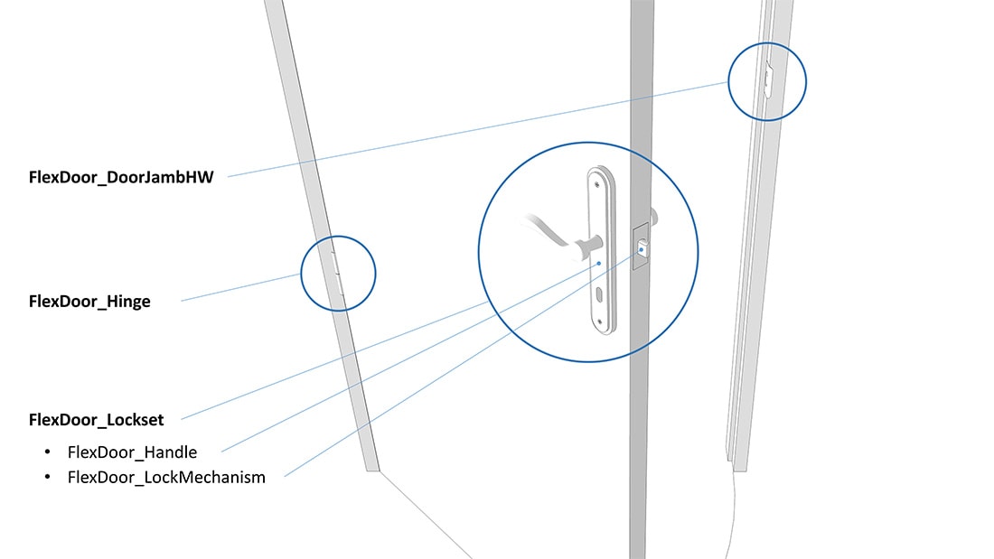
Basic hardware component types, each is interchangeable with its own type:
- FlexDoor_Hinge – Hinges (currently not fully editable).
- FlexDoor_Lockset – Includes the Handles & Lock Mechanism Components.
- FlexDoor_Handle – There are two handles – one is a mirrored copy.
- FlexDoor_LockMechanism – Anything you want to sit in between the handles.
- FlexDoor_DoorJambHW– Anything you want to fit on the Frame side.
How to Change Door Handles
Hardware can only be changed with Dynamic FlexDoor Hardware Components that have been created from within FlexDoor.
You can download FlexDoor Hardware Components from the 3DWarehouse or you can create your own Hardware Combinations.
FlexTools Hardware from 3D Warehouse
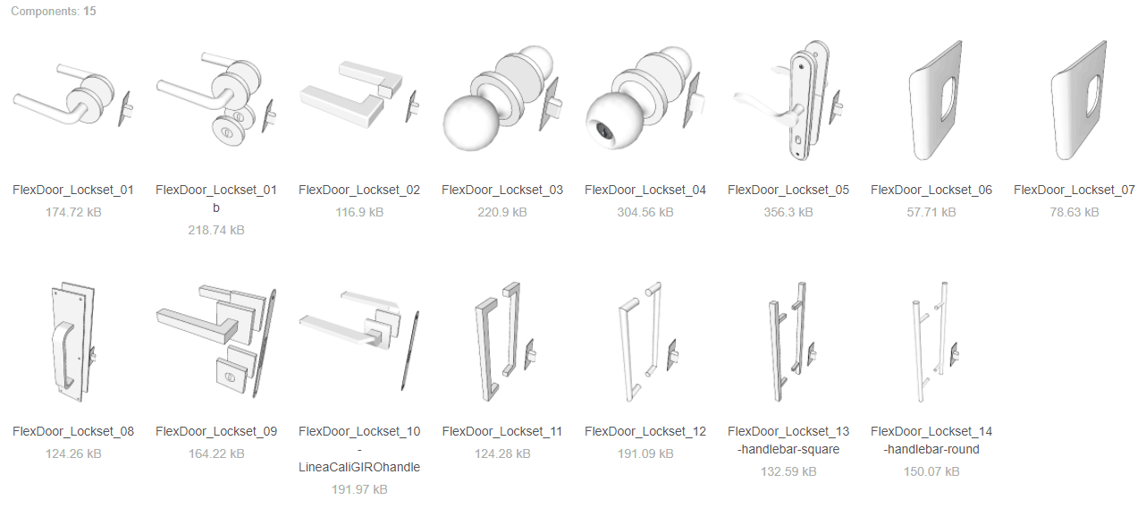
You can choose between a number of flexdoor locksets. Each lockset is a combination of 2 door handles and a locking mechanism all in one component that works dynamically with each of the Flex door components.
Option 1
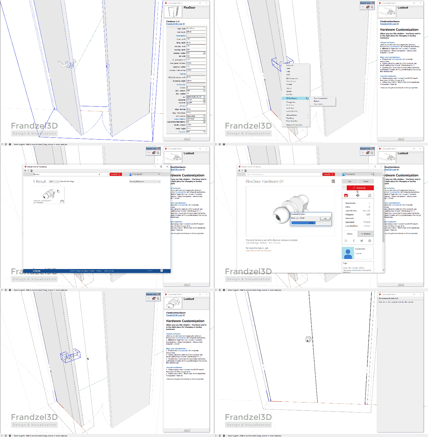
Download from the 3Dwarehouse directly from within Sketchup:
- Double click your way into the door component until you reach the lockset component.
- Right Click > 3D Warehouse > Reload... > Search for 'FlexDoor' or 'FlexTools'.
- Download the chosen lockset and it will automatically replace the existing.
- If needed - Click on the new lockset component with the interact tool to calibrate it's location.
Option 2
Download the locksets from the 3D warehouse onto your hard disk and then load them into the door manually:
- Double click your way into the door until you reach the Lockset component.
- Delete the component that is in there and insert (by drag and drop) one of the downloaded locksets.
- If needed, calibrate the new lockset's location by clicking on it with the Interact tool.
Create Your Own Hardware Combinations
You can change the handles within the ‘Lockset’ component to any shape and size you desire.
You can make your own combinations, for example:
- Handles with or without a bolt assembly,
- Different handles on each side.
You can delete or add a different ‘LockMechanism’. And more . . .
Step 1: Make sure the setup is right
When editing a Lockset always begin with these 3 very important steps:
- Under the main menu select Window > Model Info > Components > Check ‘Show component axes’
- Make sure '# doors' is set to 1, and that the door is swinging towards you.
- The handle you will be editing must be the one closest to you. It must be for a ‘Left Handed’ Handle – The opposite (mirrored) ‘Right Handed’ Handle will update itself when the editing is done.
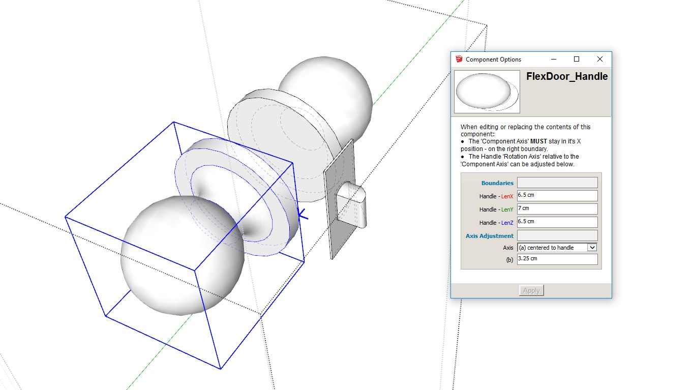
The left handed handle (Click to enlarge the picture)
Step 2: Take Measurements
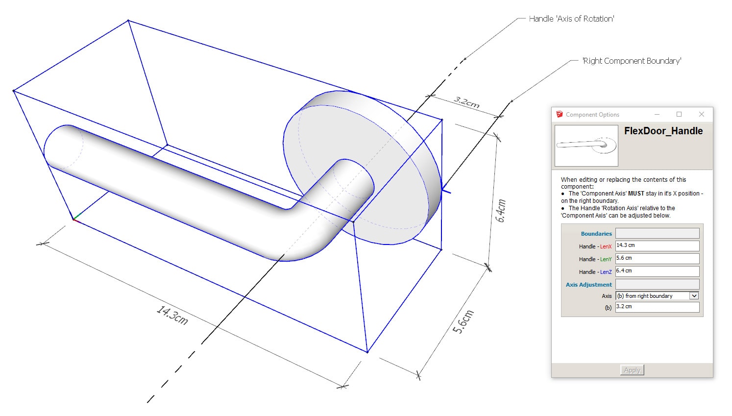
Measure and write down the LenX, LenY, LenZ boundary dimensions of the new ‘Left Handed’ Handle you want to place.

If the handle is asymmetrical/ NOT round, measure and write down the distance between the handle Axis of Rotation and the Right Component Boundary.
Taking Measurements (Click to enlarge the picture)
Step 3: Replace with a new handle you created
- Double click to enter into the 'Lockset' component.
- Select the ‘Left Handed’ Handle (closest to you).
- In the ‘Options Window’ change LenX LenY LenZ dimensions to correspond to the new Handle dimensions.
The current handle will deform - that’s OK!
- Under ‘Axis Adjustment’ - If the new handle is
- symmetrical on the YZ axis, or round like a knob – Choose ‘(a) centered‘ and ignore the next setting.
- asymmetrical - Choose ‘(b) from right boundary‘ and enter the distance you measured from the right boundary. (This setting makes sure the ‘Handle Distance’ FlexDoor setting is correct).
- Right click on the Handle and choose ‘Scale Definition’.
- Double click to enter into the handle.
- Place the new handle EXACTLY within the new LenX LenY LenZ boundaries.
- Delete the old handle.
The ‘Lockset’ is positioned according to its ‘Component Axis’ – Its axis must remain on the right boundary. Its Z position may be altered – Remember that its Z position is determined by the the ‘Handle Height’ FlexDoor setting.
The opposite (mirrored, right hand) handle will re-scale to the new scale only after it’s refreshed or if it moves. To make sure – move the mirrored handle a little in any direction – it should then re-scale and jump back into place (If not… something is wrong! – undo and restart whole edit procedure).
- Make sure to ‘Purge Unused’ to remove any remaining definitions of the old handle.
- Follow the same procedure for the Bolt component. You may also just delete the Bolt Component.
- Right click on the ‘Lockset’ component > ‘Save As’
- Done! You can now swap any ‘Lockset’ components with the one you just created.
The same procedures apply to the separate FlexDoor_DoorJambHW component. (It is visible only if ‘# doors‘ is set to 1).

